Render Engine
The render engine has two main functions. The first is to draw the frame buffer to the LCD. The second is to provide functions for drawing sprites, shapes, text etc to the frame buffer.
Render Engine Structure

Frame Buffer
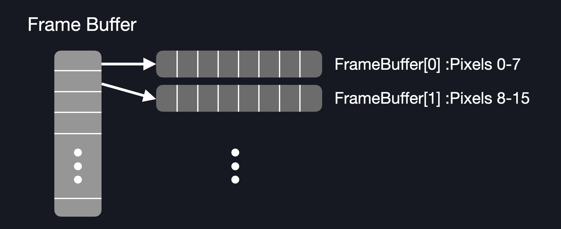
Functions such as BM_RE_drawSprite do not draw directly to the display. Instead, the function draws to a canvas called the frame buffer. This canvas is then drawn to the display via the function, BM_RE_updateDisplay.
Sprite Draw Process

The frame buffer itself is an array of bytes (uint8_t). An element of the array (a byte) stores data for 8 pixels. Since the LCD is monochromatic, there are only two colours: black and white (or 0 and 1 respectively):
Frame Buffer Format

BitMasher's display dimensions are 128 x 128 pixels. This means that there are total of 16384 pixels. Since 8 pixels can be packed into one byte, the size of the frame buffer array is 2048 bytes (or 2 kB).
Drawing Sprites
Pixel data for sprites (or graphics) are also stored as an array of bytes similarly to the frame buffer. When the BM_RE_drawSprite function is called, the following steps are taken to draw the sprite:
- Based on the x and y position of the sprite, locate the first byte in the frame buffer that needs to be modified (byte index = (16 * yPos) + (xPos / 8))
- Copy the contents of the sprite byte to the frame buffer byte. Note that if xPos is not divisible by 8 then only part of the frame buffer byte will be modified
- If all of the sprite's columns have been written, then move to the next row (yPos += 1) and recalculate the frame buffer byte index based on the new yPos value. Otherwise, go to step 4.
- Get the next frame buffer byte and copy of the contents of the next sprite byte. Note that if xPos is not divisible by 8, then the remaining bits of the previous sprite byte need to be copied to the new frame buffer byte before the bits of the new sprite byte get copied into the new frame buffer byte
- Repeat the above steps until all of the sprite's rows have been written to the frame buffer
Example
Imagine that we have a sprite that is 10 pixels in width and 2 pixels in height. We will also place the sprite in coordinates, xPos = 3 and yPos = 5. The total size of the sprite byte array is 4 bytes.
- The index of the first frame buffer byte that needs to be modified is (16 * 5) + (3 / 8) = 80
- Next, we copy the contents of our sprite byte to the frame buffer byte. However, xPos is not divisiible by 8 so we cannot copy the entire sprite byte into the frame buffer byte! We start copying the contents of the sprite byte starting at bit 3 of the frame buffer byte:
![]()
- Now that the frame buffer byte has been modified, we need to modify the next frame buffer byte. Since the first sprite byte was partially copied, we need to copy the remaining bits of the first sprite byte to the next frame buffer byte. We must also copy the contents of the second sprite byte. Note that because the sprite is 10 pixels wide, two bytes are needed to fit the data. However in the second byte, there are only 2 bits of data. The remaining bits are "don't-care" values and are not copied into the frame buffer.
![]()
- All the pixels in the first row of the sprite have been drawn. We can now move to the next row. We need to recalculate the frame buffer index which is (16 * 6) + (3 / 8) = 96. We then follow the same process as when we drew the first row:
![]()
The actual draw implementation is more complicated and considers edge cases such as when the sprite's coordinates are out of the display bounds but the overall process for drawing the sprite is largely the same as described above.
Frame Update Timer
BitMasher runs at a frame rate of 30 FPS. This means that the display is updated every 33 msec. To ensure that the frame is periodically updated, a hardware timer is used (in particular, TIMER1). When the timer expires (after 33 msec), the timer ISR will send a BM_SERVICE_UI message to the queue. This triggers scene and display updates in the currently running controller.
Display Driver
The render engine uses the display driver (MW_Driver_LS013B7DH03) which handles the low-level functions needed to transfer the frame buffer data to the display. The actual transfer occurs through SPI. The driver also sends another signal, VCOM which is responsible for removing charge build-up inside the display. The VCOM signal itself is a square wave that uses the MCU's LETIMER to generate the frequency.
Conventions
Display Coordinates
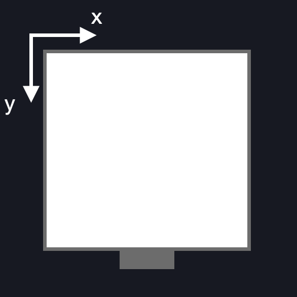
The origin of the display (and frame buffer) is the top-left corner. The x coordinate increases as a point moves further to the right and the y coordinate increases as a point moves further down the screen.
Display Origin

Pixel Colours
The LCD display considers 0 to be black and 1 to be white.
However when working with sprites, the opposite is true. 1 is considered to be black and 0 is white. This convention is subject to change however.
Masks
Masks are used to indicate a sprite's areas of transparency. If the following cloud sprite was drawn on a black background, there would be a white box surrounding the actual image of the cloud:
Cloud Sprite

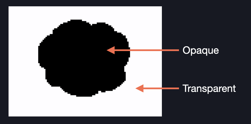
To remove the box, we use a mask:
Cloud Mask

The transparent part (which takes on the values of whatever data is in the frame buffer) is indicated by a white pixel while the opaque part (the actual cloud) is indicated by a black pixel. In this case, 1 is considered white and 0 is black.