Hardware Overview
This section outlines some of the major hardware components of BitMasher and their relations to each other. For more detailed information on the connections between subsystems, please refer to the schematic.
This overview is valid for the Proto-2 version of the BitMasher hardware. The components and connections are subject to change in future revisions.
MCU
BitMasher is powered by the EFM32PG12 microcontroller by Silicon Labs. The MCU is clocked at 40 MHz when operating at full power mode and is subject to change as the device enters various energy modes. The EFM32PG12 also features a floating point unit which is useful when applying DSP routines.
Audio Codec
BitMasher uses the Cirrus Logic CS42L52 audio codec. Audio is fed into and out of the codec via 3.5 mm audio line-in jacks. Digitized audio signals are passed to and from the MCU via I2S lines. The audio codec is set as the controller (rather than as the peripheral) and the MCU configures the codec via I2C.
Display
The display used is the Sharp LS013B7DH03, a monochrome LCD display. The MCU sends image data to the display via SPI.
User IO
BitMasher is controlled by a D-pad, A, B, Menu and Shift buttons. The buttons are active low.
Host Communication
BitMasher communicates to a host PC using the FTDI FT230 USB-UART converter. There are currently no communication protocols defined for BitMasher. This subsystem is only used for loading firmware but future revisions may extend its use.
Power
BitMasher may be powered either by 2xAAA batteries or by VBUS (USB). When powered by batteries and a USB cable is plugged in, BitMasher will automatically switch its power source to VBUS. A 2.5 V linear regulator provides power to the MCU and audio codec while a 3 V switching regulator provides power to the display.
Real-time Clock
A 32.768 crystal oscillator is connected to the MCU to enable real-time clock functionality. This oscillator is also used to time the display COM signal.
Debugging
SWD
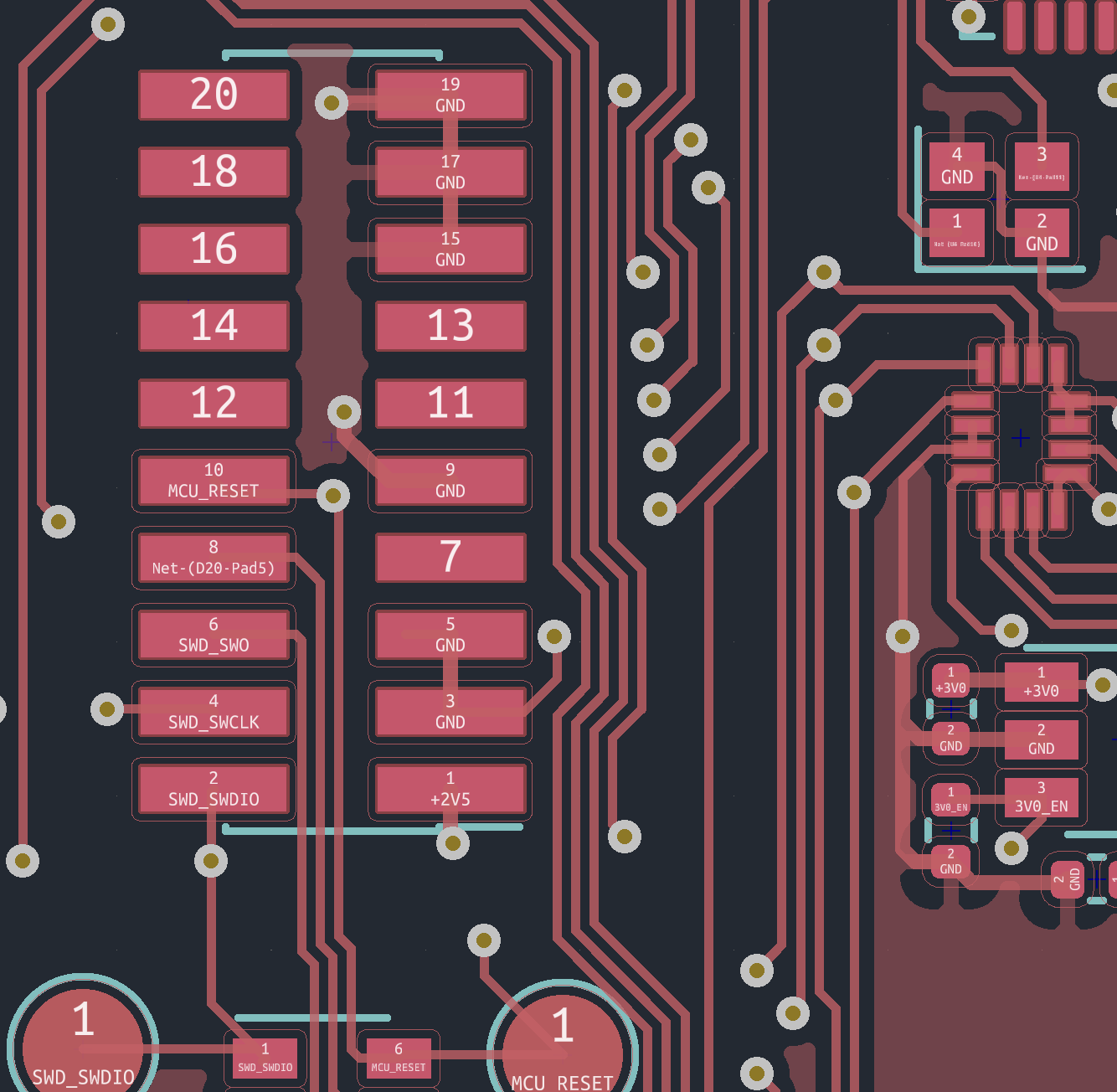
The BitMasher PCB features a SWD header for programming and debugging the MCU. When using this header to connect to a hardware debugger, use a cable such as this one which uses the correct connector.
The image below shows the association of the header pads with the SWD signal:
SWD Header Connections
Test Points
Four GPIO pins from the MCU are broken out onto test pads to enable general purpose debugging. The BM_DebugServices module in the firmware contains functions for controlling these pins.