Introduction
BitMasher is a portable audio platform with a retro-game inspired UI. It is an experiment in designing creative ways of controlling and applying audio effects to input audio through limited user inputs and a simple monochrome display.
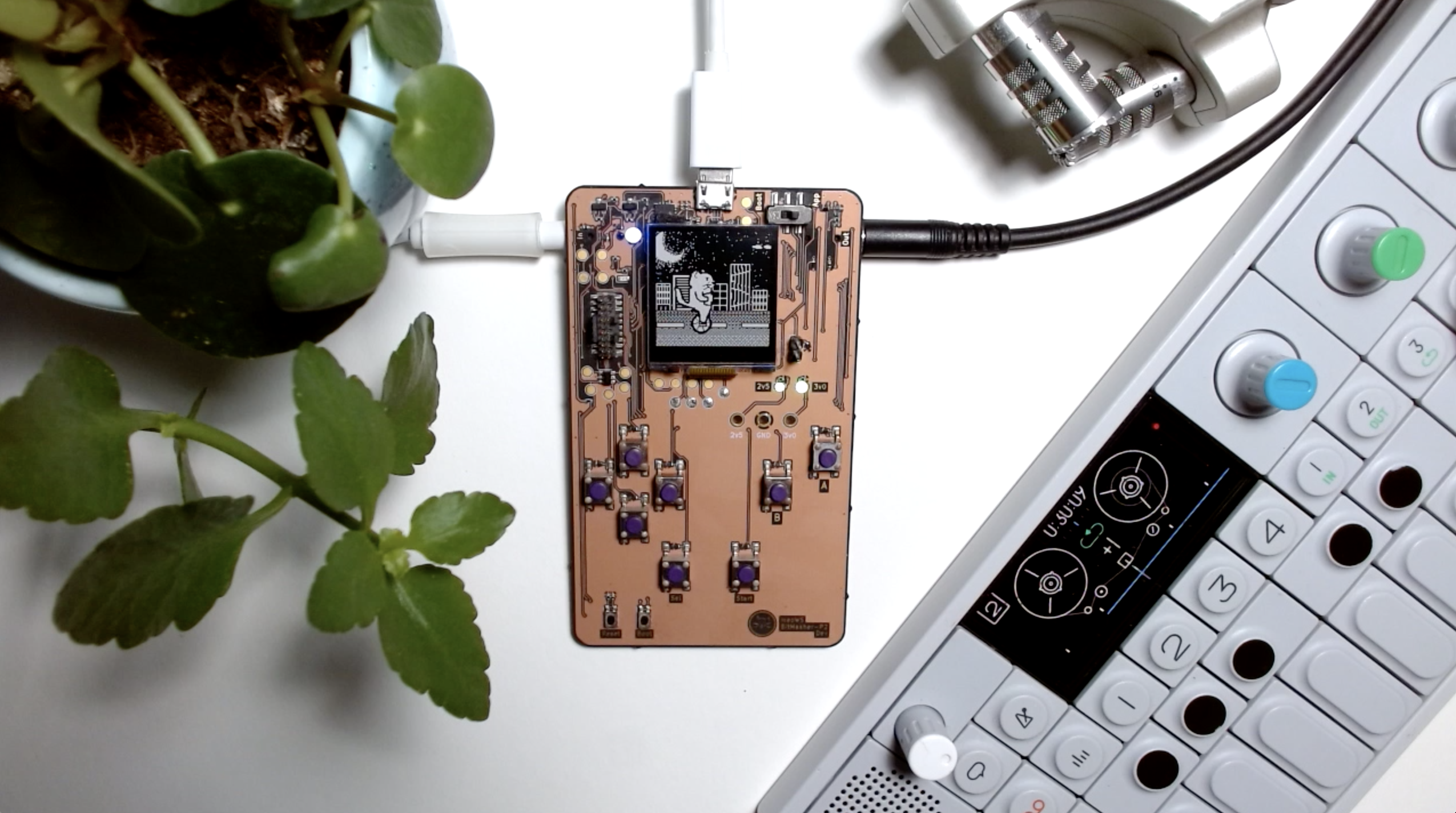
In BitMasher, the user can interact with different scenes which are tied to different audio effects (filters, bitcrushers, granularizers, doppler etc). There are four pre-packaged scenes in the device but custom scenes can be created using the BitMasher platform API. BitMasher development is not limited to running scenes however and the platform code can be used to build other audio experiences. The platform and application source code can be found in BitMasher Firmware Repository.
Hardware design files can be found here
This documentation provides an overview of the hardware and firmware systems of BitMasher, build instructions and steps to build custom scenes.
Important Notice
BitMasher is under continuous development. Its code and design is subject to frequent changes. No guarantees are made about its safety and performance. When working with audio systems, it is important to make the necessary precautions to protect your hearing. Use the BitMasher code and design files at your own risk!
License
BitMasher Source Code and Assets
BitMasher code is licensed under the MIT License
Graphical assets are under the Creative Commons Attribution-ShareAlike 3.0 License CC BY-SA 3.0
Silicon Labs Gecko SDK
BitMasher uses the Gecko SDK by Silicon Labs. Please refer to the source files in the SDK for licensing information.
Adafruit GFX Library
BitMasher uses the Classic Font font adapted from the Adafruit GFX Library which is licensed under the BSD 2-Clause License
ARM CMSIS Library
The ARM CMSIS Library is licensed under the Apache 2.0 License.
Prepackaged Scenes
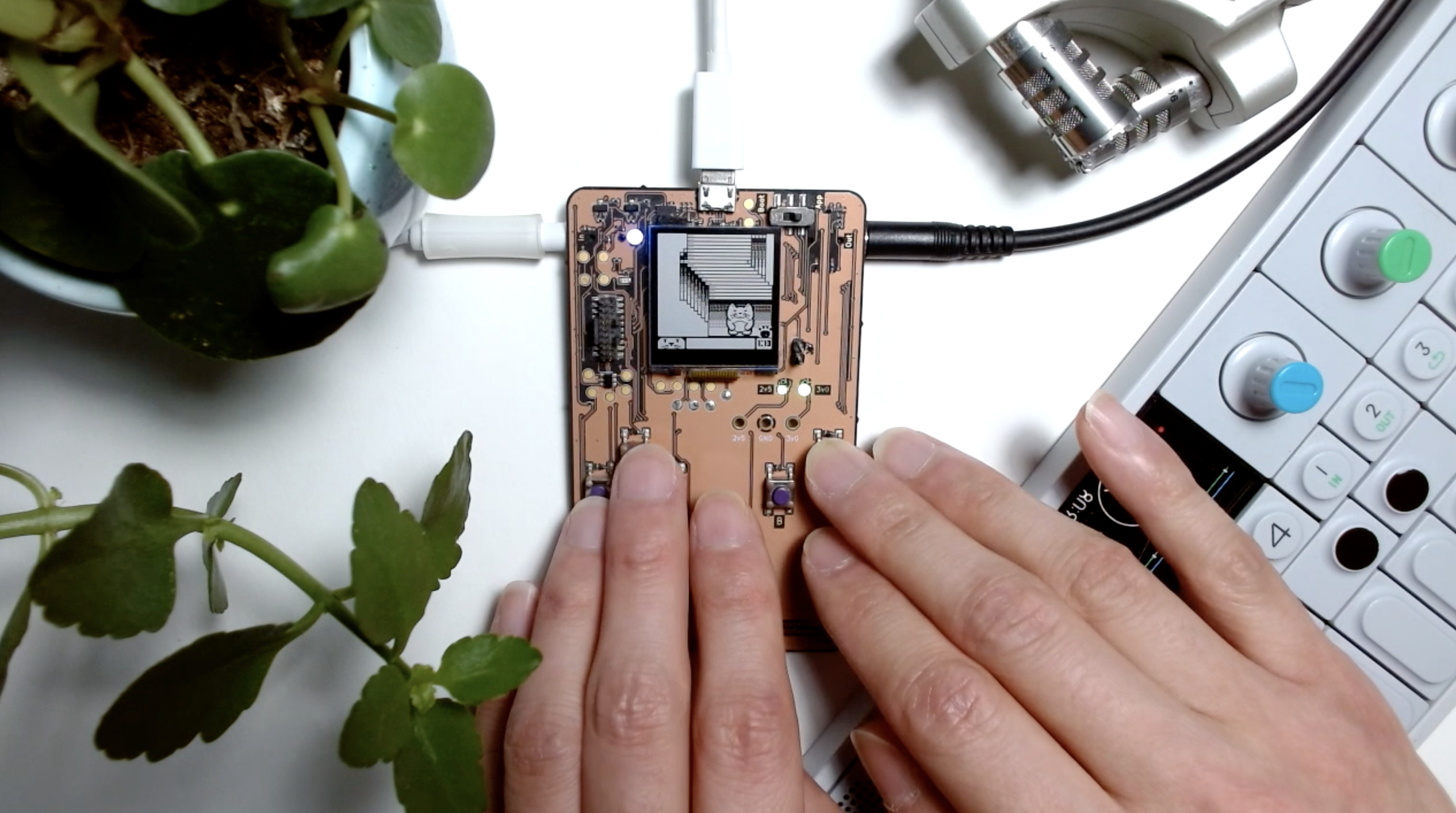
The BitMasher source code comes bundled with source code for four pre-packaged scenes - each mapped to different audio effects.
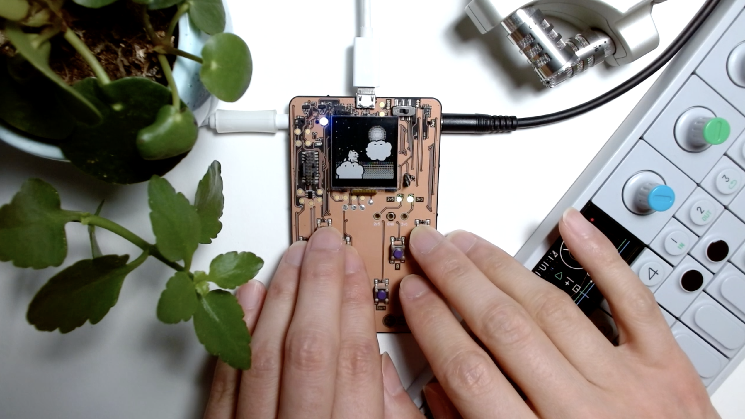
Clouds
A scene with a cat that be controlled to jump onto one of two clouds - each mapped to a low and high pass filter. Landing on a cloud will cause it to sink, changing the cutoff frequency of its associated filter.
Telephone
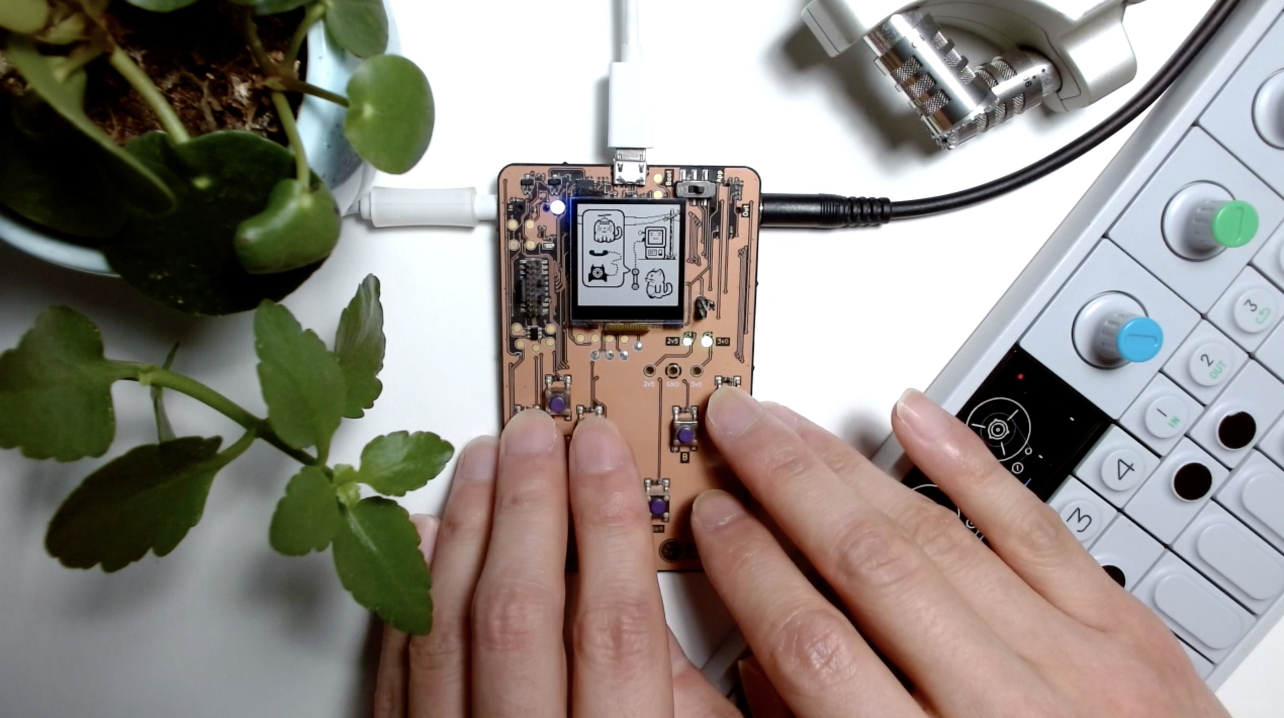
A cat using a payphone to call his friends. Beanie cat is tied to a flutter-modulator effect while spy cat is mapped to a bitcrusher effect. The calling cat itself is tied to a bandpass filter. Pressing A will trigger the effect. Pressing B will open a phone book to select which cat friend to call and the D-pad can switch between different cats and modify audio effect parameters.
Unicycle
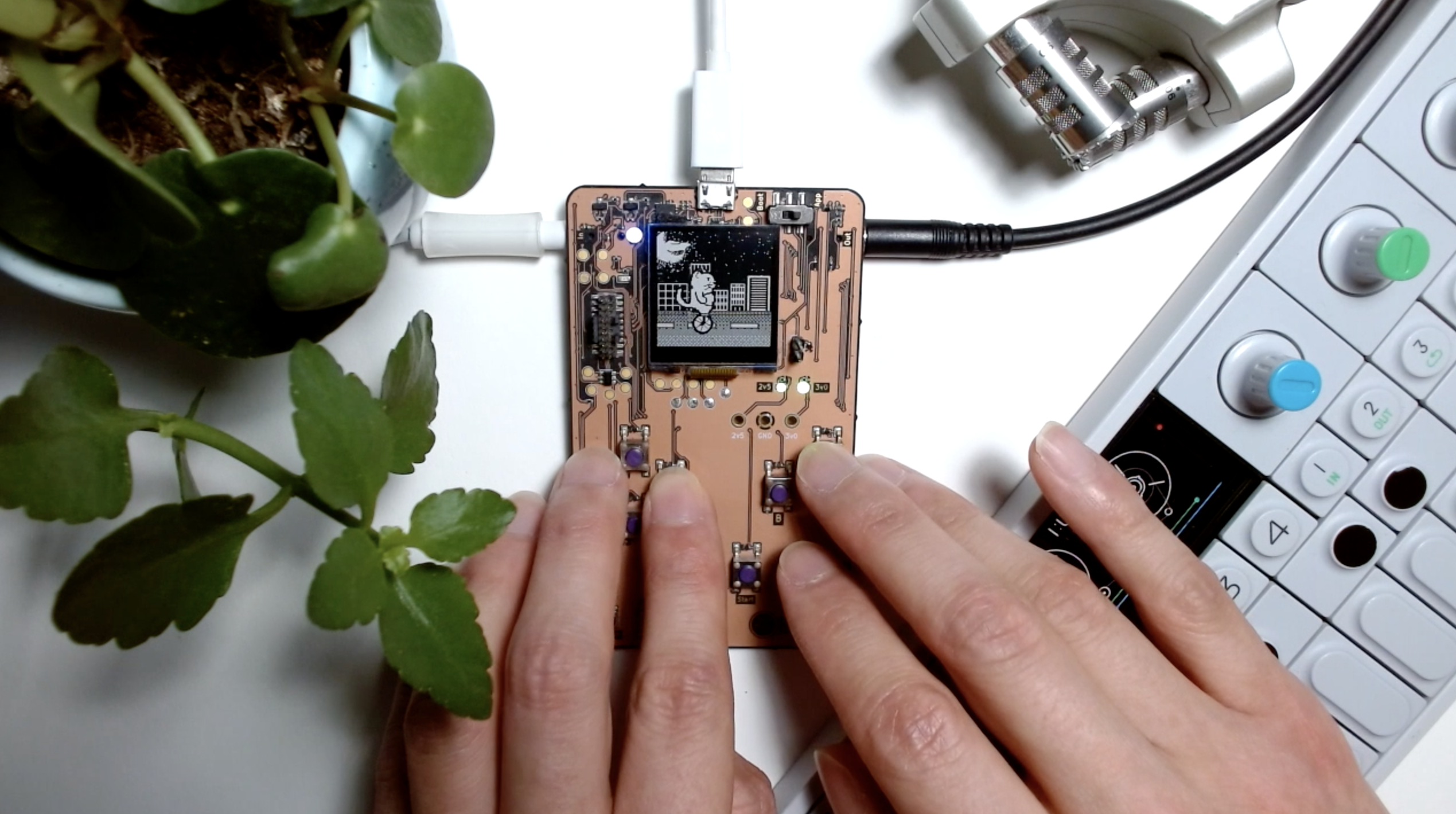
A cat riding a unicycle. Pressing right on the D-pad will move the cat forward and ramp up audio playback. Pressing left will play audio "backwards." Pressing A will make the cat pedal faster.
Glitch
A "desktop" environment where you can control the mouse and move a window around. The scene is tied to a granularizer effect.
Building and Running
Building with CMake
The easiest way to build BitMasher source code is by using CMake.
Building BitMasher requires the GNU ARM Embedded Toolchain and the ARM CMSIS library. Additionally, BitMasher depends on the MW_AudioFX library for the DSP elements which can be found here.
Once CMake and the dependencies are downloaded, set the appropriate variables in the included CMakeLists file with the correct paths:
set(TOOLCHAIN_PATH <path_to_toolchain>)
set(MW_AUDIO_FX_PATH <path_to_mw_audio_fx_files>)
set(CMSIS_PATH <path_to_cmsis_lib>)
Next, in a command line terminal go into the BitMasher directory, create a build directory and go into it:
$ mkdir build
$ cd build
Then run the CMake configuration:
$ cmake ..
Finally, build the source:
$ make all
The BitMasher.axf executable should appear in the build directory.
Building BitMasher in Release Mode
The previous instructions built BitMasher source in DEBUG mode (ie with no compiler optimizations enabled). To build with compiler optimizations (-O3), simply enter the following commands:
$ cmake .. -DCMAKE_BUILD_TYPE=Release
$ make all
Running the Executable
There are two ways to upload the BitMasher executable onto the device. The first is through a hardware debugger (JLink, JTAG etc) which will not be covered in this documentation. The second way is through the BitMasher uploader tool.
When using the uploader tool, you will not have any debugging capabilities that a hardware debugger offers (i.e. you will not be able to set breakpoints in code).
The uploader tool is a simple python script that sends the executable over a serial port using the XMODEM protocol. Therefore, before running the script, ensure that you have the pySerial and XMODEM modules installed. If you are using pip:
$ pip install pySerial
$ pip install XMODEM
Set the switch near the top-right of BitMasher to Boot and connect a USB cable from your computer to BitMasher. The device should now be in bootloader mode and nothing should appear on the screen. Next, find the name of the serial port that is connected with BitMasher. On MacOS, you can do this by typing the following in the command line:
$ ls /dev/tty.*
This will give a list of all devices. BitMasher's serial port will be named something like:
/dev/tty.usbserial-xxxxxxxx
Where xxxxxxxx is a series of alphanumeric characters.
To execute the script and send the binary, type the following into the command line:
python bm-fw-updater.py -d /dev/tty.usbserial-xxxxxxxx -f /path/to/binary/BitMasher.axf
After the upload finishes, set the top-right switch on BitMasher to App and press the reset button found on the bottom-left of the device. The binary should now run.
Hardware Overview
This section outlines some of the major hardware components of BitMasher and their relations to each other. For more detailed information on the connections between subsystems, please refer to the schematic.
This overview is valid for the Proto-2 version of the BitMasher hardware. The components and connections are subject to change in future revisions.
MCU
BitMasher is powered by the EFM32PG12 microcontroller by Silicon Labs. The MCU is clocked at 40 MHz when operating at full power mode and is subject to change as the device enters various energy modes. The EFM32PG12 also features a floating point unit which is useful when applying DSP routines.
Audio Codec
BitMasher uses the Cirrus Logic CS42L52 audio codec. Audio is fed into and out of the codec via 3.5 mm audio line-in jacks. Digitized audio signals are passed to and from the MCU via I2S lines. The audio codec is set as the controller (rather than as the peripheral) and the MCU configures the codec via I2C.
Display
The display used is the Sharp LS013B7DH03, a monochrome LCD display. The MCU sends image data to the display via SPI.
User IO
BitMasher is controlled by a D-pad, A, B, Menu and Shift buttons. The buttons are active low.
Host Communication
BitMasher communicates to a host PC using the FTDI FT230 USB-UART converter. There are currently no communication protocols defined for BitMasher. This subsystem is only used for loading firmware but future revisions may extend its use.
Power
BitMasher may be powered either by 2xAAA batteries or by VBUS (USB). When powered by batteries and a USB cable is plugged in, BitMasher will automatically switch its power source to VBUS. A 2.5 V linear regulator provides power to the MCU and audio codec while a 3 V switching regulator provides power to the display.
Real-time Clock
A 32.768 crystal oscillator is connected to the MCU to enable real-time clock functionality. This oscillator is also used to time the display COM signal.
Debugging
SWD
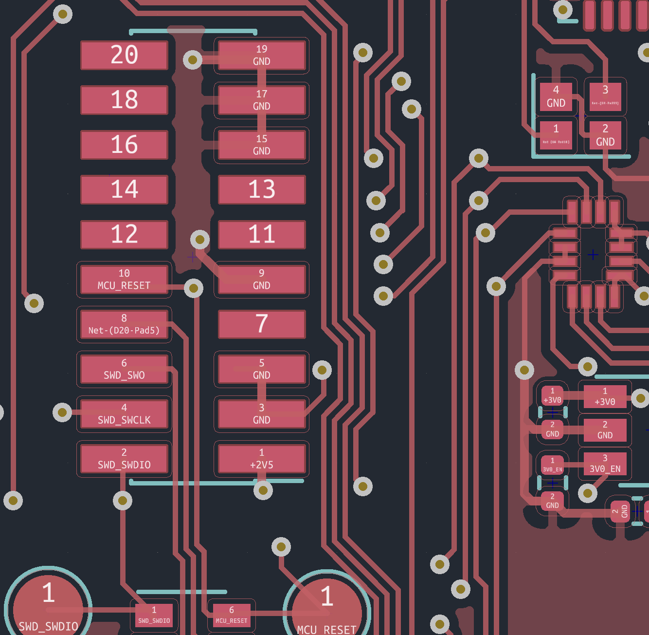
The BitMasher PCB features a SWD header for programming and debugging the MCU. When using this header to connect to a hardware debugger, use a cable such as this one which uses the correct connector.
The image below shows the association of the header pads with the SWD signal:
SWD Header Connections
Test Points
Four GPIO pins from the MCU are broken out onto test pads to enable general purpose debugging. The BM_DebugServices module in the firmware contains functions for controlling these pins.
Firmware Overview
This chapter contains details of the various components in the BitMasher firmware. It is intended for anybody who is interested in learning more about the inner workings of BitMasher.
Architecture
Basic Structure
The structure of BitMasher can be divided into two main parts: the platform and application.
The platform contains low-level code that manage the MCU's internal peripherals and the movement of data into and out of external peripherals (such as the audio codec and LCD display). It can be loosely thought of as the "kernel" or "back-end" of the system that supports the application layer.
The application is the main playable part of BitMasher. It contains the underlying code for the scenes and the controllers that run them. The application is analogous to an app that runs on your computer but in this case, there is only one app that ever runs and there is no operating system that manages the app's startup, execution and exit.
BitMasher Structure

BitMasher State Machine
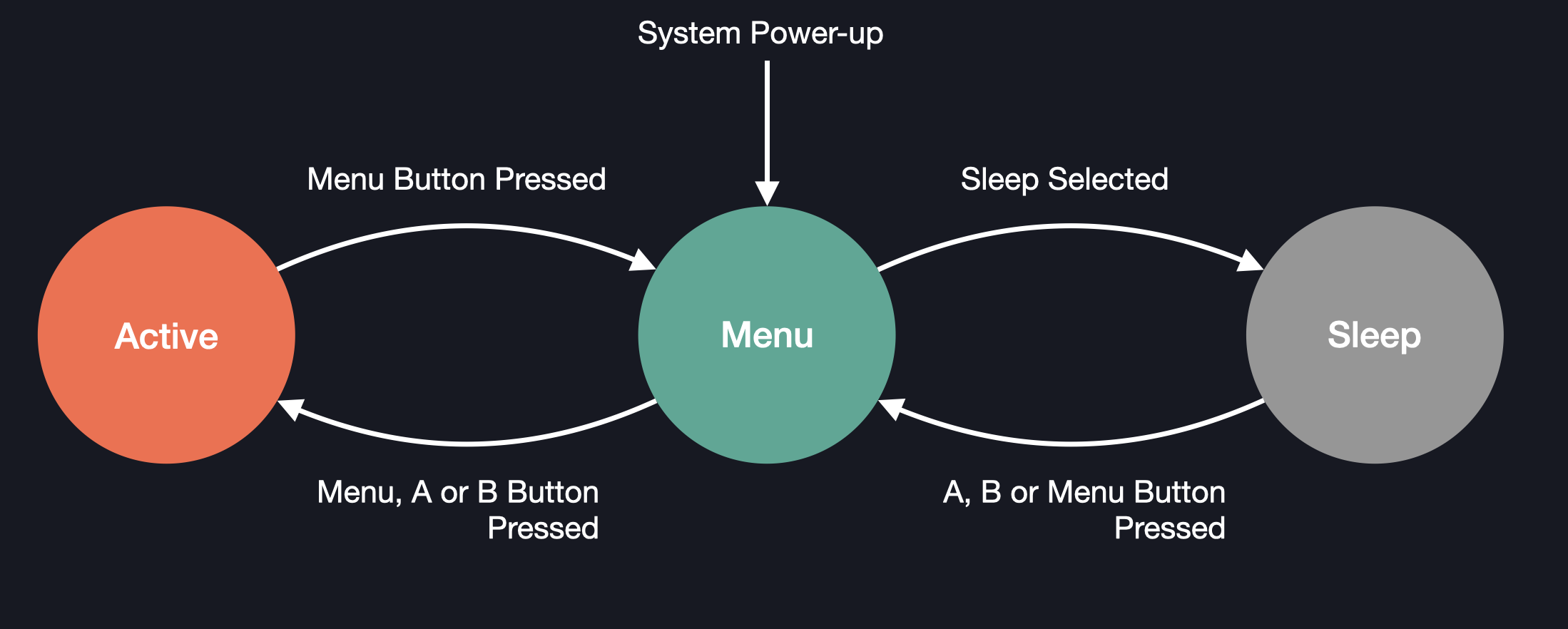
BitMasher has three states that the user can be in at any given time. Each state is managed by a controller. When the user interacts with a scene, the system is in the active state which is managed by the active controller (BM_Controller_Active). When the user is in the menu, the system is in the menu state (BM_Controller_Menu). Finally, when the device is sleeping/in low-power mode, it is in the sleep state (BM_Controller_Sleep). The diagram below shows the different states and the events that cause the transitions between the states:
BitMasher State Machine Diagram
Communicating Audio and Update Events
While BitMasher is running, the audio and rendering engines operate in the background. However, when an audio buffer is filled or a scene update/frame render needs to be performed, there needs to be some way of communicating these events/requests to the controllers. In BitMasher's case, the audio and render engines pass messages into a queue which are read and processed by the controller.
Audio/Update Events Handling
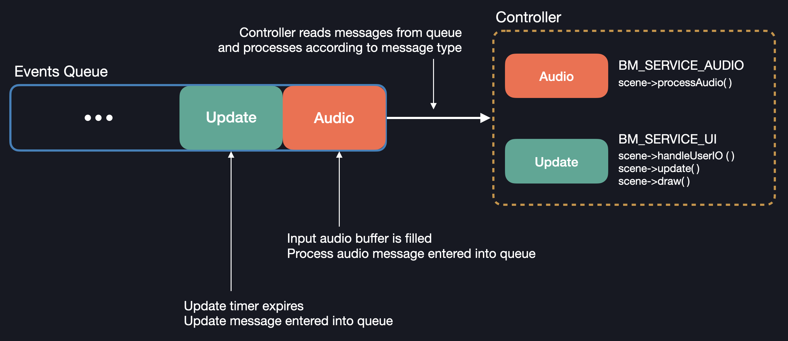
More information about message handling is covered in the Controllers section.
Audio Engine
The audio engine is responsible for transporting audio samples into and out of the MCU, codec and controllers.
Audio Engine Structure

Operation
Sample Movement
Movement of Input and Output Samples

When the codec transfers an input audio sample to the MCU, the sample is first shifted into the MCU's USART RX buffer. Once all of the bits of the sample are transferred, the sample is automatically transferred into the input buffer. This process repeats until the input buffer is filled.
When the input buffer is full, an interrupt is triggered and the corresponding ISR sends a BM_SERVICE_AUDIO message into the queue (which is read by the currently running controller). The message also contains a pointer to the input buffer so that the audio processing functions know where to find the input data.
Similar to the movement of input samples, the MCU takes a sample from an output buffer of processed samples and transfers it into the USART TX buffer which is then automatically transferred to the codec. Once the output buffer is emptied, the MCU moves to the next buffer of output samples and the emptied buffer is ready to be filled with input samples.
The transfer of samples between the RX/TX buffers in the USART peripheral and the input/output buffers is handled automatically by the Direct Memory Access (DMA) module. Without the DMA module, the CPU is responsible for transferring the samples into and out of the buffers, resulting in reduced efficiency.
The physical transfer of input and output samples to and from the MCU actually happens at the same time! I2S has lines reserved for both the input and output data (typically labelled as SDIN, SDOUT lines).
The codec samples audio at a frquency of 32 kHz.
Buffers
In order to avoid interruptions in audio as buffers moved to different stages, BitMasher has three buffers that move between audio input, processing and output stages. This way, all stages can operate simultaneously and not wait for buffers to be transferred to them from previous stages.
Movement of Buffers

Other Functions
The audio engine also allows configuration of various parameters in the codec (e.g. gain and EQ settings). Configuration is done through I2C.
Codec Driver
The audio engine uses the codec driver (MW_Driver_CS42L52) which handles the low-level functions needed to communicate and transfer samples to/from the codec. The driver handles the necessary MCU peripheral configurations (e.g. USART, I2C, clocking) as well as codec setup.
Clocking
The codec requires a 12.288 MHz clock signal (MCLK). To generate this signal, the MCU uses the signal from the low frequency (32.768 kHz) crystal oscillator and routes it to a phase lock loop where the frequency is increased to the required 12.288 MHz.
MCLK Clocking

Render Engine
The render engine has two main functions. The first is to draw the frame buffer to the LCD. The second is to provide functions for drawing sprites, shapes, text etc to the frame buffer.
Render Engine Structure

Frame Buffer
Functions such as BM_RE_drawSprite do not draw directly to the display. Instead, the function draws to a canvas called the frame buffer. This canvas is then drawn to the display via the function, BM_RE_updateDisplay.
Sprite Draw Process

The frame buffer itself is an array of bytes (uint8_t). An element of the array (a byte) stores data for 8 pixels. Since the LCD is monochromatic, there are only two colours: black and white (or 0 and 1 respectively):
Frame Buffer Format
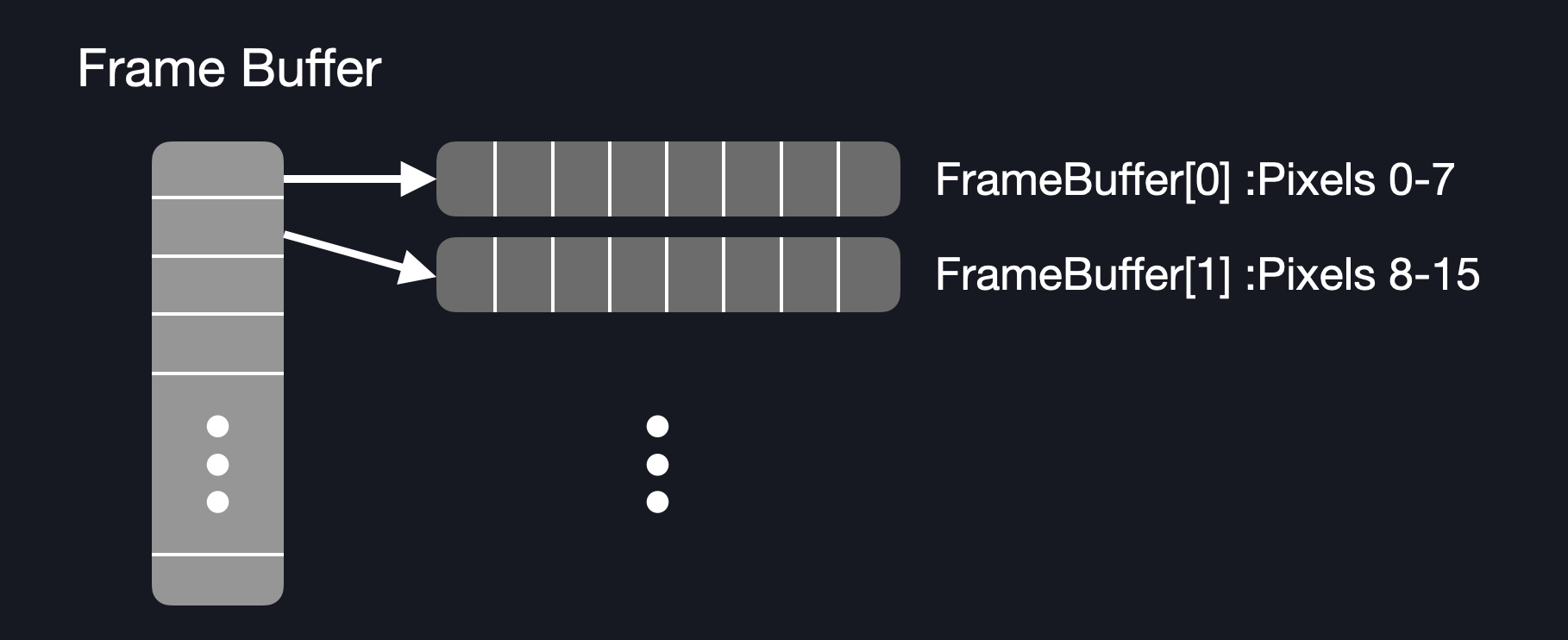
BitMasher's display dimensions are 128 x 128 pixels. This means that there are total of 16384 pixels. Since 8 pixels can be packed into one byte, the size of the frame buffer array is 2048 bytes (or 2 kB).
Drawing Sprites
Pixel data for sprites (or graphics) are also stored as an array of bytes similarly to the frame buffer. When the BM_RE_drawSprite function is called, the following steps are taken to draw the sprite:
- Based on the x and y position of the sprite, locate the first byte in the frame buffer that needs to be modified (byte index = (16 * yPos) + (xPos / 8))
- Copy the contents of the sprite byte to the frame buffer byte. Note that if xPos is not divisible by 8 then only part of the frame buffer byte will be modified
- If all of the sprite's columns have been written, then move to the next row (yPos += 1) and recalculate the frame buffer byte index based on the new yPos value. Otherwise, go to step 4.
- Get the next frame buffer byte and copy of the contents of the next sprite byte. Note that if xPos is not divisible by 8, then the remaining bits of the previous sprite byte need to be copied to the new frame buffer byte before the bits of the new sprite byte get copied into the new frame buffer byte
- Repeat the above steps until all of the sprite's rows have been written to the frame buffer
Example
Imagine that we have a sprite that is 10 pixels in width and 2 pixels in height. We will also place the sprite in coordinates, xPos = 3 and yPos = 5. The total size of the sprite byte array is 4 bytes.
- The index of the first frame buffer byte that needs to be modified is (16 * 5) + (3 / 8) = 80
- Next, we copy the contents of our sprite byte to the frame buffer byte. However, xPos is not divisiible by 8 so we cannot copy the entire sprite byte into the frame buffer byte! We start copying the contents of the sprite byte starting at bit 3 of the frame buffer byte:
![]()
- Now that the frame buffer byte has been modified, we need to modify the next frame buffer byte. Since the first sprite byte was partially copied, we need to copy the remaining bits of the first sprite byte to the next frame buffer byte. We must also copy the contents of the second sprite byte. Note that because the sprite is 10 pixels wide, two bytes are needed to fit the data. However in the second byte, there are only 2 bits of data. The remaining bits are "don't-care" values and are not copied into the frame buffer.
![]()
- All the pixels in the first row of the sprite have been drawn. We can now move to the next row. We need to recalculate the frame buffer index which is (16 * 6) + (3 / 8) = 96. We then follow the same process as when we drew the first row:
![]()
The actual draw implementation is more complicated and considers edge cases such as when the sprite's coordinates are out of the display bounds but the overall process for drawing the sprite is largely the same as described above.
Frame Update Timer
BitMasher runs at a frame rate of 30 FPS. This means that the display is updated every 33 msec. To ensure that the frame is periodically updated, a hardware timer is used (in particular, TIMER1). When the timer expires (after 33 msec), the timer ISR will send a BM_SERVICE_UI message to the queue. This triggers scene and display updates in the currently running controller.
Display Driver
The render engine uses the display driver (MW_Driver_LS013B7DH03) which handles the low-level functions needed to transfer the frame buffer data to the display. The actual transfer occurs through SPI. The driver also sends another signal, VCOM which is responsible for removing charge build-up inside the display. The VCOM signal itself is a square wave that uses the MCU's LETIMER to generate the frequency.
Conventions
Display Coordinates
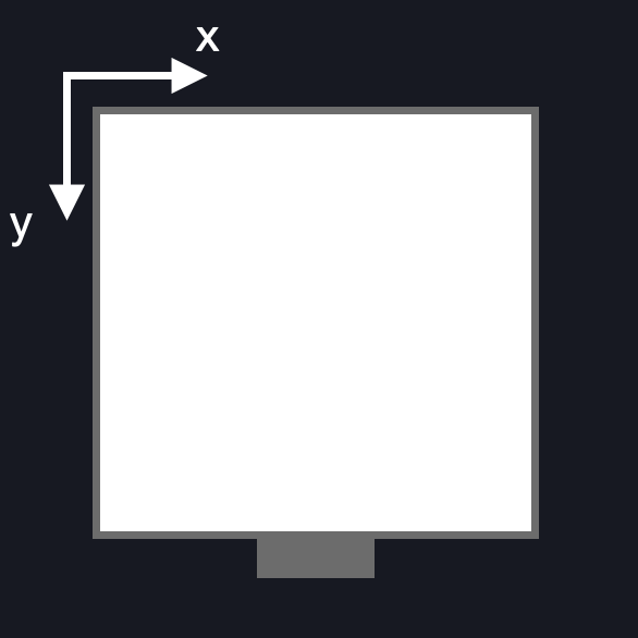
The origin of the display (and frame buffer) is the top-left corner. The x coordinate increases as a point moves further to the right and the y coordinate increases as a point moves further down the screen.
Display Origin
Pixel Colours
The LCD display considers 0 to be black and 1 to be white.
However when working with sprites, the opposite is true. 1 is considered to be black and 0 is white. This convention is subject to change however.
Masks
Masks are used to indicate a sprite's areas of transparency. If the following cloud sprite was drawn on a black background, there would be a white box surrounding the actual image of the cloud:
Cloud Sprite

To remove the box, we use a mask:
Cloud Mask
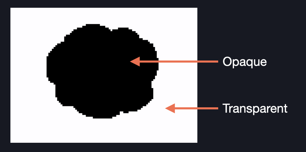
The transparent part (which takes on the values of whatever data is in the frame buffer) is indicated by a white pixel while the opaque part (the actual cloud) is indicated by a black pixel. In this case, 1 is considered white and 0 is black.
User IO
BitMasher has eight buttons that the user can press to interact with the device: a D-Pad (up, down, left, right), A, B, Menu and Shift buttons.
Button States and Voltages
The buttons are directly connected to the MCU's GPIO pins and are active low. This means that the MCU pin will read 2.5 V when a button is not pressed and 0 V when it is pressed:
Pin Voltage Levels for Button Interactions

Querying Button States
BM_UserIOServices contains functions that query the states of the buttons. There are however two types of states that can be read from the button: current state and edge state.
Current State
BM_UserIO_getButtonState reads the state of a single button at any given time. Alternatively, the state of all buttons can be read using BM_UserIO_getAllButtonStates which expects a pointer to a uint32_t variable, buttonStates in its parameter. The states of all of the buttons are packed into buttonStates - that is, each bit represents the state of a button:
Button Mapping on BM_UserIO_getAllButtonStates Output

The following example first reads the state of the A button before reading the state of all buttons:
uint32_t buttonState = 0;

//  Read the state of the A button
BM_UserIO_getButtonState(BM_USERIO_A, &buttonState);
if (!buttonState)
    //  Button is pressed
else
    //  Button is released

//  Read the state of all buttons and check the state of button A
BM_UserIO_getAllButtonStates(&buttonState);
if (!(buttonState & (1 << BM_USERIO_A))
    //  A Button is pressed
Note that if the button is pressed, buttonState should return 0 as the signals are active low.
Edge State
There may be times where reading the button's state transition may be preferred. The functions, BM_UserIO_getButtonEdgeState and BM_UserIO_getAllButtonEdgeStates can be used to detect whether or not a state transition has occurred.
These functions expect a BM_UserIO_Edge parameter which can be either BM_USERIO_RISING or BM_USERIO_FALLING. Rising Edge means that the button is released while Falling Edge means that the button is pressed:
Voltage Signals of Button Presses/Releases

The example code checks for a falling edge transition on button A:
uint32_t buttonEdgeState = 0;

//  Get the edge state of button A
BM_UserIO_getButtonEdgeState(BM_USERIO_A, &buttonEdgeState, BM_USERIO_FALLING);
if (buttonEdgeState)
    //  Falling edge is detected

//  Get the edge state for all buttons
BM_UserIO_getAllButtonEdgeStates(&buttonEdgeState, BM_USERIO_FALLING);

//  Check to see if button A has a falling edge
if (buttonEdgeState & (1 << BM_USERIO_A))
    //  Falling edge detected on button A
Getting edge transition information relies on the fact that BM_UserIO_update must be called periodically. However, when creating scenes, you will not need to worry about calling this function as the controllers typically do this for you.
Clocking
Clocks are an important part of an MCU and its peripherals. CM_ClockTree contains functions that configure the MCU's clock sources and clock settings for the peripherals used.
Clock Sources
BitMasher uses two external crystal oscillators. The main oscillator is clocked at 40 MHz and drives the CPU and most of the MCU's peripherals. The secondary, low-frequency oscillator is clocked at 32.768 kHz and drives the MCU's low-energy peripherals, codec MCLK generation and the real-time clock module:
BitMasher Clock Tree
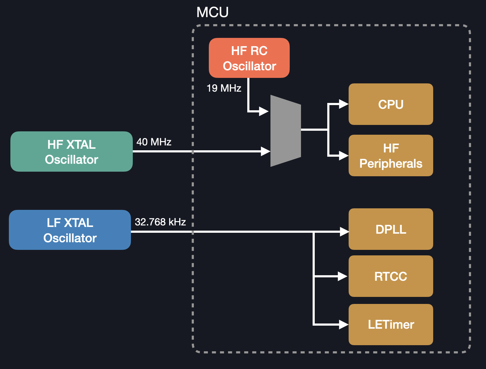
BitMasher also has the option to use the internal oscillator clocked at 19 MHz. This is intended for when BitMasher enters a low-power state.
While a function to enter the low-power clocking state exists, it is not yet fully functional.
Power Management
The power management module, BM_PowerManagement controls power to the display and can manage transitions between low and full-power states.
Voltage Scaling
The MCU can change its internal voltage. The lower the voltage, the less power is drawn. However, lower operating voltages means that the operating frequency is also reduced, reducing the system performance. Therefore, low-power states are best reserved for extended periods of inactivity where DSP routines are not run.
While functions to enter into low-power states are available, they are not yet ready to be used!
Real-time Clock
BitMasher features a clock which is displayed when the device is put to sleep. This clock is driven by the real-time clock and calendar module (RTCC). Functions to setup and query the RTCC module are found in BM_RTCModule. Clocking for the real-time clock module is derived from the external low-frequency (32.768 kHz) oscillator.
Querying the Time
The functions, BM_RTCModule_getCurrentTimeHMS and BM_RTCModule_getCurrentTimeBCD can be used to get the current time. There are two formats for representing time: Hour-Minute-Second (HMS) and Binary Coded Decimal (BCD).
HMS
In HMS representation, the hour, minute and second is assigned its own variable and is most convenient to work with:
typedef struct
{
    int32_t hour;
    int32_t minute;
    int32_t second;
}BM_RTCModule_TimeHMS;
Calling BM_RTCModule_getCurrentTimeHMS will return the current time in HMS. A pointer to an instance of BM_RTCModule_TimeHMS is required as a parameter input.
BCD
In BCD representation, each digit in the hour, minute and second is assigned its own variable:
BCD Representation
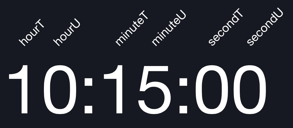
typedef struct
{
    int32_t hourT;
    int32_t hourU;
    int32_t minuteT;
    int32_t minuteU;
    int32_t secondT;
    int32_t secondU;
}BM_RTCModule_TimeBCD;
While this may seem inconvenient at first, the advantage of BCD is that each digit can be packed into a single 32-bit variable and easily transferred to the MCU's RTCC registers.
The time can be converted between different representations by using BM_RTCModule_convertBCDToHMS and BM_RTCModule_convertHMSToBCD functions.
Setting the Time
BM_RTCModule_setTime is used to set the time. This function expects the time in HMS format.
Counter
In addition to telling the time, the BM_RTCModule also features a counter that increments every minute (every minute, an interrupt is triggered which increments the counter). This counter is planned to be used in a timeout system that puts the device to sleep after a period of inactivity.
Interrupts
Since BitMasher uses many of the MCU's peripherals, interrupts are extensively used. To avoid scattering ISRs directly called by the CPU in different source files, they are consolidated in BM_ISR. However, the actual user-defined routines can be defined in separate source files. As a result, there is a registration process when creating an ISR for a particular peripheral.
For example, TIMER1 is used as the frame update (or VSYNC) timer for the render engine. The user-defined ISR is written in BM_RenderEngine.c:
void BM_RE_VSYNCISR()
{
  TIMER_IntClear(TIMER1, TIMER_IFC_OF);
  BM_ServiceQueue_addItemToServiceQueue(BM_SERVICE_UI, NULL);
}
However, when the TIMER1 interrupt is triggered, the function, TIMER1_IRQHandler() in BM_ISR.c is executed. To ensure that BM_RE_VSYNCISR is executed, the function must be registered with BM_ISR:
BM_ISR_Timer_registerTIMER1ISR(BM_RE_VSYNCISR);
This ensures that when TIMER1_IRQHandler is executed, BM_RE_VSYNCISR is also executed.
Debugging
BitMasher comes with debugging and instrumentation tools found in BM_DebugServices and can be used to profile performance or to indicate points of interest.
Debug Ports
Four GPIO pins are broken out into test points on the PCB and each test point is assigned a label:
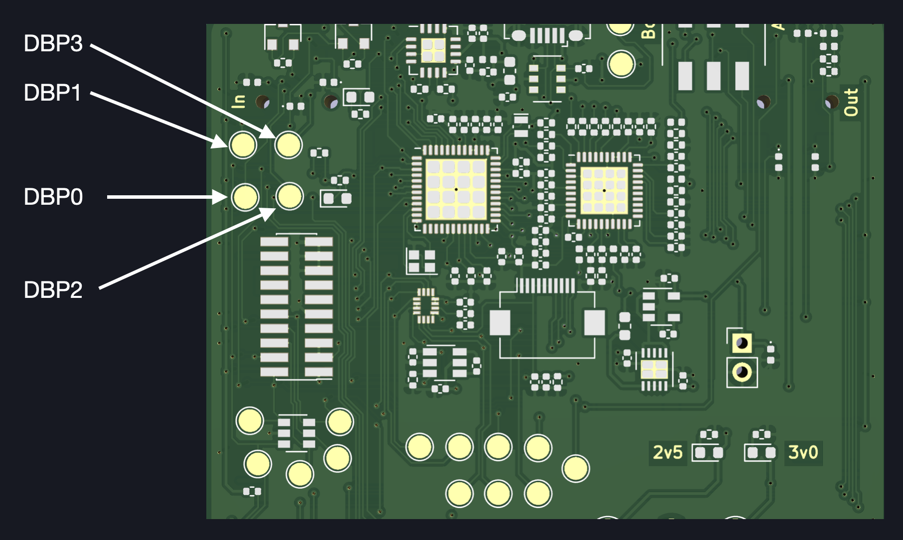
The test points can be toggled high or low using BM_DebugServices_set, BM_DebugServices_clear or BM_DebugServices_toggle and measured with a logic analyzer, multimeter or oscilloscope:
//  Example Use Case
//  DBP0 is set high and then low after function_to_be_time() finishes.
//  The pulse width can be measured with an oscilloscope or logic analyzer to determine the execution time
BM_DebugServices_set(DBP0);

function_to_be_timed();

BM_DebugServices_clear(DBP0);
Timers
The debug module also features timers that may be used to profile performance. The timers use the WTIMER peripheral and can be accessed through the functions BM_DebugServices_startPerformanceTimer and BM_DebugServices_getTimeElapsed. Note that the latter returns the time elapsed in microseconds:
//  Example Use Case
BM_DebugServices_startPerformanceTimer(1);

function_to_be_timed();

int32_t time_in_usec = 0;
BM_DebugServices_getTimeElapsed(&time_in_usec);
BM_DebugServices_startPerformanceTimer(0);  //  Stop timer
LED Indicator
A red LED indicator can also be controlled through the functions BM_DebugServices_setAlertLED and BM_DebugServices_clearAlertLED.
The debug ports, timers and LEDs available are subject to change with later PCB revisions.
Controllers
Controllers can be thought of as the supporting layer of the BitMasher application. It communicates with the platform components and drives the scenes that run on top of it. As mentioned in the Architecture section, BitMasher runs on a state machine and each state is assigned its own controller.
Most controllers run in an infinite loop, reading audio/UI update messages from the queue and processing them accordingly. Each controller has their own way of processing these messages.
Active Controller
This is the main controller (BM_Controller_Active) that drives the playable scenes. The controller maintains a list of playable scenes in the _scenes array and tracks the current scene through _sceneIndex.
When a BM_SERVICE_UI message is read from the queue, the active controller will perform the following tasks:
- Call BM_UserIO_update( ) to detect rising/falling edge transisitons (see UserIO).
- Check to see if the Menu button has been pressed (via handleUserIO( ))
- Call the current scene's handleUserIO, update and draw callback functions
- Draw the frame buffer to the display
When a BM_SERVICE_AUDIO message is read, the controller first converts the input buffer of int16_t samples to float32_t before passing the buffer of floating point values to the scene's processAudio callback function.
Reading Messages from the Queue

Scene Callback Functions
A scene must implement the below callback funtions in order to work with the active controller
init();
update();
draw();
handleUserIO();
reset();
processAudio();
More information about creating custom scenes can be found in Making Your Own Scenes.
Entering the Menu
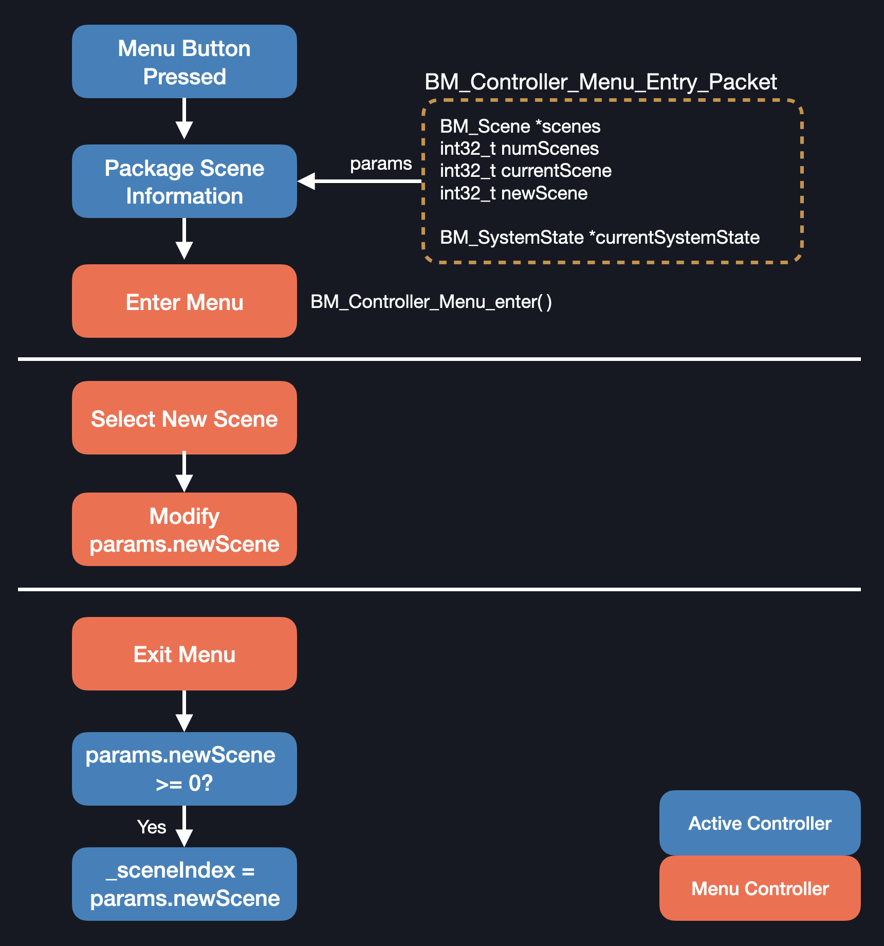
When the Menu button is pressed, the BM_Controller_Active_enterMenu function is executed. The menu system needs information about the list of available scenes and the current scene. This information is packaged in an instance of a BM_Controller_Menu_Entry_Packet struct and passed into the menu controller.
When exiting from the Menu, the active controller checks to see if the newScene member in BM_Controller_Menu_Entry_Packet is a non-negative number. If it is, then this means that the scene has changed and _sceneIndex is updated to reflect the new current scene.
Menu Entry Process
Menu Controller
The menu controller works nearly identically to the active controller. The menu controller also runs scenes but in this context, the scenes are the menu pages instead of the playable scenes that the active controller runs. The menu controller also handles BM_SERVICE_AUDIO messages but does not process the input buffers.
Menu Scenes
There are two main menu scenes that the Menu Controller runs. The first is the Main Menu Scene. This is where the user can select a new scene to run as well as enter the settings menu and put the system to sleep. The second is the Settings Scene, where the user can make changes to the audio settings and the time.
The Menu Controller manages scenes through a stack data structure. At the bottom of the stack is the Main Menu Scene. If the user enters the Settings Menu, the first settings scene/page is pushed onto the stack. More scenes are pushed onto the stack as the user moves deeper into the settings options.
When the user exits a settings scene, it is popped off the stack.
Menu Stack Changes as the User Navigates through Various Pages

The stack is implemented as an array with predetermined size to avoid the need for dynamic memory allocation.
Sleep Controller
The sleep controller works quite differently from the Active and Menu Controllers. The controller still runs an infinite loop but does not process queue messages. This is because the audio and render engines are stopped before entering the sleep controller so there are no messages in the queue to process.
The sleep controller updates the clock (displayed on the LCD) and shuts down the CPU (and other peripherals). Every minute, the CPU wakes up, updates the display and goes back to sleep.
Making Your Own Scenes
While the BitMasher source code comes with pre-packaged scenes, custom scenes may also be made. This chapter details the necessary steps for making scenes by example.
Example Scene
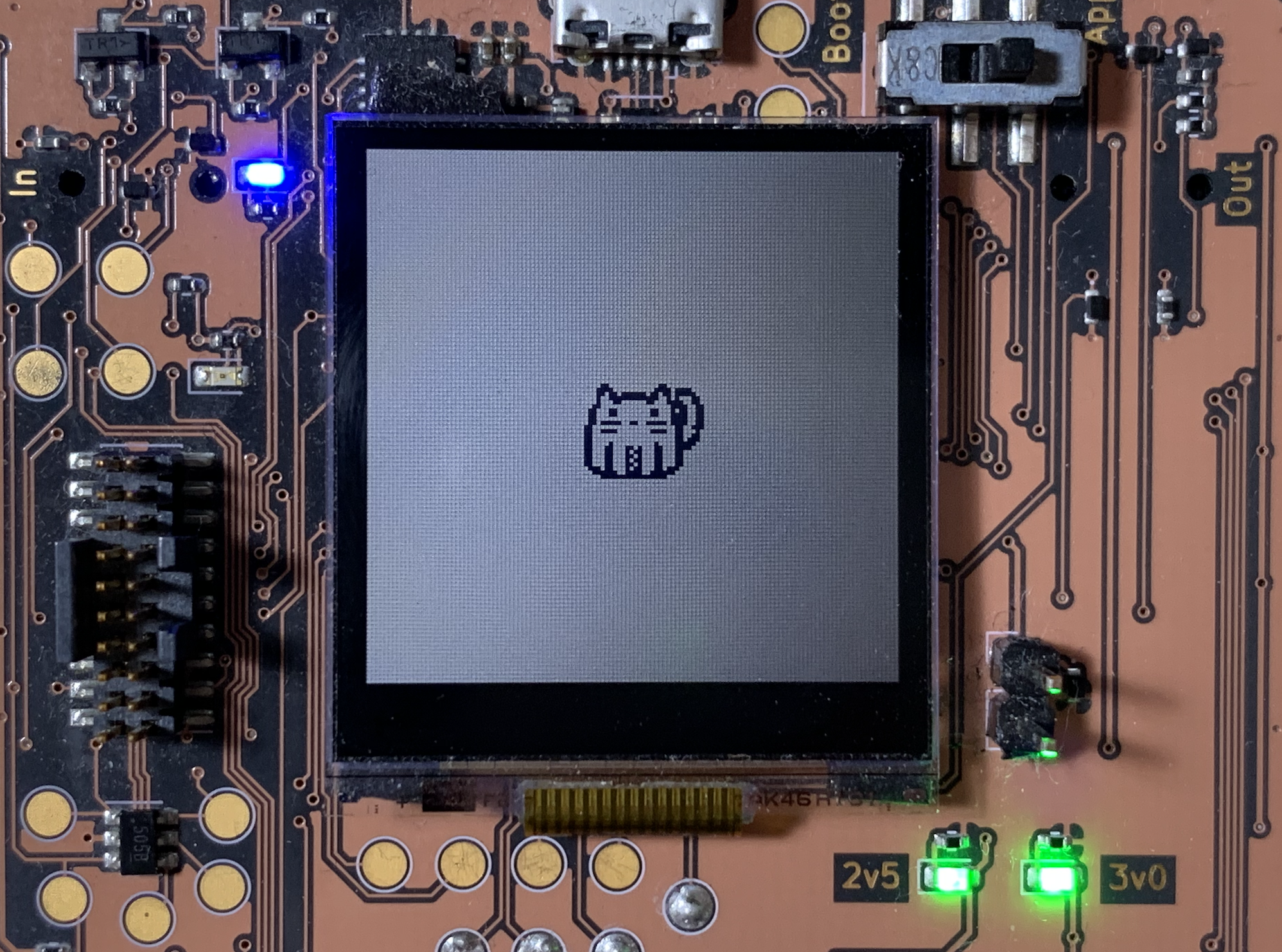
The scene that we will make is a simple pad consisting of a cat that can be moved around the screen. We will call this scene CatPad The cat's position on the screen is mapped to different parameters of a filter. The cat's horizontal position is mapped to the cutoff frequency while the vertical position is mapped to the filter's Q factor (resonance).
Scene Basic Structure
To start, let's go through the basic structure of a scene. Generally, the programmer is free to organize the source code of their scene however they want. There are however some necessary callbacks and boilerplate code that need to be written.
First, create a folder called CatPad under App/Scenes then create a header and source file called BM_Scene_CatPad.h and BM_Scene_CatPad.c. The header file should look like the following:
//  BM_Scene_CatPad.h
#pragma once

#include "arm_math.h"
#include "BM_Scene.h"           //  Contains typedefs necessary for building scenes
#include "BM_ErrorCodes.h"      //  Error codes
#include "BM_RenderEngine.h"    //  For calling rendering functions
#include "BM_Common.h"          //  For calling convenience macros and fade in/out envelopes if the scene crossfades audio in some way
#include "BM_Sprite.h"          //  Contains struct definitions for storing sprites
#include "BM_UserIOServices.h"  //  For calling functions that read button states

//  For this scene, we will use the SV Filter and also import misc utilities
//  Include the appropriate audio effects for your particular scene here
#include "MW_AFXUnit_SVFilter.h"
#include "MW_AFXUnit_MIscUtils.h"

//  Include sprite header for the scene
//  We haven't created this file yet so you will get compiler errors.  We will cover this in the next section
#include "BM_Assets_CatPad.h"


//  A scene must have an initialization function with the following signature
BM_Error BM_Scene_CatPad_init(BM_Scene *scene);

// Necessary callbacks to implement
void BM_Scene_CatPad_update(void* data);
void BM_Scene_CatPad_draw();
void BM_Scene_CatPad_processAudio(float32_t *buffer, const size_t bufferSize);
void BM_Scene_CatPad_handleUserIO();
void BM_Scene_CatPad_reset();

// Other functions and variables necessary for the scene (up to the programmer)
As a convention, scenes and their associated variables/functions are prefixed by BM_Scene_[Scene Name]. This is to avoid name clashes with similarly named functions across other source files.
The include directives bring in necessary headers needed for the scene to operate. Since we want to incorporate an SV Filter into our scene, we will include the MW_AFXUnit_SVFFilter.h header. This header is part of the AudioFXUnits library.
A scene must include an initialize function (which is called by the active controller on start up) and must accept a pointer to a BM_Scene instance (provided by the active controller) and return an error code.
The rest of the functions are the callback functions that our scene must implement.
Before we implement the functions, let's first talk about importing graphical assets into BitMasher.
Importing Graphical Assets
Workflow
BitMasher itself does not have any functionality for drawing sprites or backgrounds on-device. They must be drawn on a separate program and then exported as a bmp or png file.
Assets Import Workflow
![]()
Converting Images to Bytes
BitMasher does not accept an image file directly. The file must be converted into a raw stream of bytes that is copied into an assets source file. The convertImage.py script does this conversion for us. Note that running the script requires Python 3, the imageio and Numpy modules.
To convert the image, execute the script:
$ python convertImage.py -f <path/to/cat.png> -s
The -s flag indicates that we are converting a sprite image as opposed to a background or sprite mask. The script should output the image in byte format as well as its dimensions. We are now ready to integrate the sprite into the scene.
Importing the Cat
Create a header file called BM_Assets_CatPad.h and add it into the Assets folder. Create the following declarations in the file:
//  BM_Assets_CatPad.h
#pragma once

#include "arm_math.h"           //  Contains type definitions (uint8_t, int32_t etc)

extern uint8_t BM_Assets_CatPad_cat[];      //  Array that will store the cat's bitmap byte data
extern int32_t BM_Assets_CatPad_catWidth;   //  Cat's width in pixels
extern int32_t BM_Assets_CatPad_catHeight;  //  Cat's height in pixels
Then, define the variables in the corresponding source file. This is where you will copy the byte output from the python script into the BM_Assets_CatPad_cat array:
//  BM_Assets_CatPad.c
#include "BM_Assets_CatPad.h"

uint8_t BM_Assets_CatPad_cat[] =
{
    0x30, 0x0, 0xc, 0x0,
    0x78, 0x0, 0xde, 0x3,
    0xd8, 0x7e, 0xdb, 0x7,
    0xc8, 0xff, 0x53, 0xc,
    0x88, 0x81, 0xf1, 0xc,
    0xc, 0x0, 0xe0, 0x19,
    0xc6, 0x0, 0xa3, 0x19,
    0xc6, 0x0, 0xe3, 0x19,
    0x6, 0x0, 0xe0, 0x19,
    0xf6, 0x99, 0xef, 0x19,
    0x3, 0x0, 0xc0, 0x1c,
    0xf3, 0x0, 0xcf, 0x8,
    0x3, 0x0, 0xc0, 0xc,
    0x3, 0x0, 0xc0, 0xe,
    0x43, 0x0, 0xc2, 0x7,
    0x63, 0x2c, 0xc6, 0x3,
    0x63, 0x34, 0xc6, 0x0,
    0x63, 0x2c, 0xc6, 0x0,
    0x63, 0x34, 0xc6, 0x0,
    0x63, 0x2c, 0xc6, 0x0,
    0x6e, 0x34, 0x76, 0x0,
    0xfc, 0x3c, 0x3f, 0x0,
    0xf0, 0xff, 0xf, 0x0
};

int32_t BM_Assets_CatPad_catWidth = 29;
int32_t BM_Assets_CatPad_catHeight = 23;
Now that we have imported our cat, let's move onto initializing the scene.
Initializing the Scene
The first step in implmenting our scene is to create the initialization function. This function takes a pointer to a BM_Scene instance (provided by the active controller) and returns a BM_Error error code.
The initialization function is responsible for assigning the pointers to the callback functions, initializing audio effects and other necessary initializations that may be needed.
Creating Internal Variables
Before we write the init function, let's add a few variables and definitions that we will be making use of later in this tutorial - namely, the filter parameters and our cat's velocity:
//  BM_Scene_CatPad.c
#include "BM_Scene_CatPad.h"

#define BM_SCENE_CATPAD_MIN_FC 100.f
#define BM_SCENE_CATPAD_MAX_FC 2000.f

#define BM_SCENE_CATPAD_MIN_Q 0.7f
#define BM_SCENE_CATPAD_MAX_Q 16.f

#define BM_SCENE_CATPAD_VELOCITY 2.f    //  Set the cat's velocity to 2 pixels per frame change

//  Note that these variables are file-scope variables (static)
static MW_AFXUnit_SVFilter _filter;     //  Instance of the SV Filter
As convention, file-scope variable names (marked as static) are prefixed with an underscore, _.
Creating a Sprite Instance
Since we will be adding a sprite (the cat) to the screen, we should create a BM_Sprite instance. This step is not strictly necessary but typically sprites will move around the screen which will require variables to track its current position and velocity (among other things). Instead of individually creating these variables, it is more convenient to wrap this information into a struct like BM_Sprite:
//  BM_Scene_CatPad.c

// --snip--

static MW_AFXUnit_SVFilter _filter;

static BM_Sprite _catSprite;    //  BM_Sprite instance that will store data about the cat sprite
Creating the init Function
Let's start writing the initialization function:
BM_Error BM_Scene_CatPad_init(BM_Scene *scene)
{
    if (scene == NULL)
        return BM_NULLPTR;

    return BM_NO_ERR;
}
Initializing the Filter
The first thing that we will do is initialize our filter:
BM_Error BM_Scene_CatPad_init(BM_Scene *scene)
{
    //  --snip--

    //  Initialize filter
    //  Sampling frequency is defined in BM_Common.h as FS
    int32_t success = MW_AFXUnit_SVFilter_init(&_filter, MW_AFXUNIT_SVFILTER_LPF, FS, BM_SCENE_CATPAD_MIN_FC, BM_SCENE_CATPAD_MIN_Q);
    if (!success)
        return BM_AFXUNIT_INIT_FAIL;

    return BM_NO_ERR;
}
To initialize our filter, we call the MW_AFXUnit_SVFilter_init() function which expects a pointer to our filter instance, _filter, the type of filter (low-pass), sampling frequency, cutoff frequency and Q factor. BitMasher's sampling rate is defined in BM_Common.h as FS (32 kHz).
Initializing the Sprite
The next step is to assign values to our _catSprite struct:
BM_Error BM_Scene_CatPad_init(BM_Scene *scene)
{
    //  --snip--

    //  Initialize _catSprite members
    _catSprite.currentBitmap = BM_Assets_CatPad_cat;
    _catSprite.currentMask = NULL;
    _catSprite.width = BM_Assets_CatPad_catWidth;
    _catSprite.height = BM_Assets_CatPad_catHeight;
    _catSprite.currentXPos = 0.0;
    _catSprite.currentYPos = 0.0;

    return BM_NO_ERR;
}
The BM_Sprite struct contains many members used for different situations but as a basic start, we will only define where the byte data is (currentBitmap), its initial position on the screen (top-left corner) and its dimensional information. currentMask is a pointer to byte data that contains information about a sprite's transparent sections but we will set it to NULL here.
Assigning Callback Functions
The last step is to assign the callback functions in the BM_Scene instance passed to the init function:
BM_Error BM_Scene_CatPad_init(BM_Scene *scene)
{
    //  --snip--

    //  Assign pointers to the callback functions
    scene->update = &BM_Scene_CatPad_update;
    scene->draw = &BM_Scene_CatPad_draw;
    scene->processAudio = &BM_Scene_CatPad_processAudio;
    scene->handleUserIO = &BM_Scene_CatPad_handleUserIO;
    scene->reset = &BM_Scene_CatPad_reset;

    //  Give the scene a name and the pointer to its icon bitmap (NULL)
    scene->sceneName = "Cat Pad";
    scene->iconBitmap = NULL;

    return BM_NO_ERR;
}
In addition to specifying the callback functions, we are also specifying the scene name. In BitMasher's menu system, a scene is typically represented through an icon image. This is optional however and in this example, we will not supply an icon and set iconBitmap to NULL. In the menu, we should see our scene represented as a box with the text, Cat Pad.
Now that we have written our initialization function, we need to actually implement the callback functions starting with the BM_Scene_CatPad_draw() function.
Drawing Sprites
Now that we have converted our cat bitmap into its raw bytes and created a BM_Sprite container that holds information about our cat sprite, the next step is to draw it on the screen.
Creating the Draw Function
All of the graphics that are present in the scene are drawn via the draw function. The active controller will call the current scene's draw function where graphics are writen to a frame buffer before being rendered onto the screen. Let's create our draw function in BM_Scene_CatPad.c after BM_Scene_CatPad_init():
//  BM_Scene_CatPad.c
#include "BM_Scene_CatPad.h"

//  --snip--

//  Draw function (after init)
void BM_Scene_CatPad_draw()
{
    //  First, draw a blank background
    BM_RE_drawLightBackground();

    //  Draw the cat
    BM_RE_drawSprite(   _catSprite.currentBitmap,
                        _catSprite.currentMask,
                        _catSprite.currentXPos,
                        _catSprite.currentYPos,
                        _catSprite.width,
                        _catSprite.height
                    );
}
That's it!
First, we create a fresh canvas by calling BM_RE_drawLightBackground. Then we draw our cat using BM_RE_drawSprite. The _catSprite instance already contains information needed by the function parameters so we pass in the structure's relevant members (currentBitmap, currentXPos etc) into the function.
We would now have a cat that appears on the screen but it does not do much of anything right now. We want to be able top move the cat around the screen as we press the D-pad buttons so our next step is to write code that will handle button press events.
Handling Button Presses
Up to this point, we have initialized our scene and drew a cat on the screen but we cannot do any more than that! In this section, we will add button handling and let the user move the cat around the screen when they press the D-pad buttons.
Creating the IO Handler Callback
To handle button presses, we will need to create the BM_Scene_CatPad_handleUserIO callback function in our scene:
//  BM_Scene_CatPad.c

// --snip--

void BM_Scene_CatPad_handleUserIO()
{

}
We can use the functions in BM_UserIOServices to detect any button presses that occur. There are different ways of detecting button presses but the function that we will use is BM_UserIO_getButtonState(). This function simply reads whether or not a given button is pressed as opposed to reading the transition from not-pressed to pressed.
Let's use BM_UserIO_getButtonState to read the states of the D-pad buttons:
//  BM_Scene_CatPad.c

//  --snip--

void BM_Scene_CatPad_handleUserIO()
{
    uint32_t buttonState = 0;

    //  Read D-pad buttons, UP, DOWN, LEFT and RIGHT
    BM_UserIO_getButtonState(BM_USERIO_UP, &buttonState);
    if (buttonState == 0)
        BM_Sprite_setVelocity(&_catSprite, _catSprite.dx, -BM_SCENE_CATPAD_VELOCITY);
    else
    {
        BM_UserIO_getButtonState(BM_USERIO_DOWN, &buttonState);
        if (buttonState == 0)
            BM_Sprite_setVelocity(&_catSprite, _catSprite.dx, BM_SCENE_CATPAD_VELOCITY);
        else
            BM_Sprite_setVelocity(&_catSprite, _catSprite.dx, 0);
    }

    BM_UserIO_getButtonState(BM_USERIO_LEFT, &buttonState);
    if (buttonState == 0)
        BM_Sprite_setVelocity(&_catSprite, -BM_SCENE_CATPAD_VELOCITY, _catSprite.dy);
    else
    {
        BM_UserIO_getButtonState(BM_USERIO_RIGHT, &buttonState);
        if (buttonState == 0)
            BM_Sprite_setVelocity(&_catSprite, BM_SCENE_CATPAD_VELOCITY, _catSprite.dy);
        else
            BM_Sprite_setVelocity(&_catSprite, 0, _catSprite.dy);
    }
}
BM_UserIO_getButtonState() expects a direction and a pointer to a uint32_t variable that stores the state of the button, buttonState. When the user presses a button, its state changes from HIGH (2.5V) to LOW (0V) - hence, the button is active low. Therefore, when a button is pressed, we expect buttonState to be 0. This is why the if-statement checks that buttonState is false (or, 0).
The velocity of the sprite is set using BM_Sprite_setVelocity(). When the up or down button is pressed, we do not want to modify the cat's horizontal velocity. Therefore, we pass in the cat's horizontal (or dx) value for the x velocity parameter while the y velocity is set to BM_SCENE_CATPAD_VELOCITY value that we defined earlier.
Likewise, when setting the horizontal velocities, we want to leave the y-velocities unmodified.
We have written code to handle button presses, but our cat will not move cross the screen yet! Next, we need to write the scene's update function.
Updating the Scene
Now that we have our cat displayed on screen and code written to handle button presses, we need to glue these together so that the user's actions actually do something. This is where the update function comes in. Let's start implementing the function:
void BM_Scene_CatPad_update(void* data)
{
    BM_Sprite_update(&_catSprite);   //  Move the cat by number of pixels defined by its velocity

    //  Ensure that the cat does not move outside the screen
    if (_catSprite.currentXPos < 0)
        _catSprite.currentXPos = 0;

    if ((_catSprite.currentXPos + _catSprite.width) >= BM_DISPLAY_WIDTH)
        _catSprite.currentXPos = BM_DISPLAY_WIDTH - _catSprite.width;

    if (_catSprite.currentYPos < 0)
        _catSprite.currentYPos = 0;

    if ((_catSprite.currentYPos + _catSprite.height) >= BM_DISPLAY_HEIGHT)
        _catSprite.currentYPos = BM_DISPLAY_HEIGHT - _catSprite.height;

    //  Set the cutoff frequency and Q of the filter based on the cat's horizontal and vertical position position
    const float newFc = MW_AFXUnit_Utils_mapToRange(_catSprite.currentXPos, 0, BM_DISPLAY_WIDTH, BM_SCENE_CATPAD_MIN_FC, BM_SCENE_CATPAD_MAX_FC);
    const float newQ = MW_AFXUnit_Utils_mapToRange(_catSprite.currentYPos, 0, BM_DISPLAY_HEIGHT, BM_SCENE_CATPAD_MIN_Q, BM_SCENE_CATPAD_MAX_Q);
    MW_AFXUnit_SVFilter_changeParameters(&_filter, MW_AFXUNIT_SVFILTER_LPF, FS, newFc, newQ);
}
In the BM_Scene_CatPad_handleUserIO function that we created in the previous chapter, we set the velocity of the cat according to the D-pad button pressed. In order for the cat's coordinates to change, its sprite must be updated using the BM_Sprite_update() function.
Since the cat has the potential to move off-screen, there is some bounds checking that must be done. When working with multiple sprites, wrapping the bounds checking code into its own function may be helpful.
Next, we want to re-calculate the filter's coefficients based on the cat's position on screen. To do this, we use the MW_AFXUnit_Utils_mapToRange() function to map the cat's position on the screen to a filter cutoff/Q value.
MW_AFXUnit_Utils_mapToRange() is part of the MW_AFXUnit_MiscUtils library in MW_AFXUnits
The filter parameters are changed via the MW_AFXUnit_SVFilter_changeParameters() function. Note that the update function is periodically called and if the cat has not changed its position between multiple calls to update(), re-calculating coefficients can be an inefficient use of processor cycles. Re-calculating the filter coefficients when the cat's position has changed is a more efficient approach.
Finally, we can move the cat around the screen and change filter parameters but the filter will not be applied to the input audio! To apply the filter, we need to write the processAudio function.
Applying the Filter to the Audio
The active controller periodically calls a scene's processAudio() function and supplies a pointer to a buffer of audio samples that the scene should process. In our scene, we need to pass the input buffer to the filter:
void BM_Scene_CatPad_processAudio(float32_t *inputBuffer, const size_t bufferSize)
{
    MW_AFXUnit_SVFilter_process(&_filter, inputBuffer, bufferSize);
}
We are almost finished writing the code for this scene. There is one more callback function that needs to be implemented, the reset callback.
Implementing Reset
When the user changes scenes, the current scene's reset function is called before loading the new scene.
The reset function is used to set a scene's internal states (variables) back to initial values. In the case of our scene, we want to reset the cat's coordinates back to (0, 0):
void BM_Scene_CatPad_reset()
{
    BM_Sprite_setPosition(&_catSprite, 0, 0);
    MW_AFXUnit_SVFilter_reset(&_filter);
}
Additionally, we are resetting the internal states of our filter.
Finally we have finished writing the code for our scene. The last step is to register our scene so that the active controller can run it.
Registering the Scene
Now that we have all of the code written for our scene, the last step is to make the active controller aware of it, therefore being able to play the scene and select it from the menu screen. To do this, we need to register our scene.
Scene registration is done in the BM_SceneRegister_registerScenes() function found in the BM_SceneRegister.c file:
BM_Error BM_SceneRegister_registerScenes()
{
    BM_ASSERT(BM_Controller_Active_registerScene(&BM_Scene_Clouds_init));
    BM_ASSERT(BM_Controller_Active_registerScene(&BM_Scene_Phone_init));
    BM_ASSERT(BM_Controller_Active_registerScene(&BM_Scene_Unicycle_init));
    BM_ASSERT(BM_Controller_Active_registerScene(&BM_Scene_Glitch_init));

    return BM_NO_ERR;
}
An important note is that a maximum of 4 scenes are allowed to be on the device. Therefore, if there are already 4 scenes defined in this function, you will need to remove one scene. For now, we will remove all of the scenes and register our custom scene:
BM_Error BM_SceneRegister_registerScenes()
{
    BM_ASSERT(BM_Controller_Active_registerScene(&BM_Scene_CatPad_init));

    return BM_NO_ERR;
}
To register a scene, we call the function BM_Controller_Active_registerScene() which expects a function pointer to our scene's init function. We encapsulate this function call in a BM_ASSERT macro to catch any failures that may occur. If registration fails, then the system will enter into an infinite loop.
We also need to include the BM_Scene_CatPad.h header in BM_SceneRegister.h:
#include "BM_Controller_Active.h"
#include "BM_ErrorCodes.h"
#include "BM_Common.h"

//  Include header files to your scenes here
#include "BM_Scene_CatPad.h"
That is everything that we need to do for our custom scene! After compiling and loading the executable onto the device, we should be able to play the scene!